Line Following Drone
May 25, 2018
| Key Skills & Tools | ||
|---|---|---|
| Programming (C) | Programming (Java) | |
| Autodesk Eagle | CAD (Onshape) | |
| Motor Control | Microcontrollers (PIC32) | |
| Feedback Control (PID) | Electronics | |
| 3D Printing | Laser Cutting | |
| Communications (Serial) | Communications (USB) | |
| Communications (SPI) | Communications (I2C) | |
| Android Studio | MPLAB Harmony | |
| IMU |
Repository
Introduction
On this project I designed a chassis using CAD modeling, 3D printing, and laser cutting; designed a PCB for a PIC32 microcontroller using Autodesk Eagle and soldered components into place; created a program in Java to run on an Android phone and locate a red line with the onboard camera; created a program in C to run on the PIC32 and use the location of that red line to apply PID control to individual wheel motors in order to make the drone follow the line; experimented with a number of potentially useful components, including making a custom HID mouse based on IMU readings, using an LCD display for various data output functions, and reading to and from SPI and I2C expansion chips to make more communications ports available.
Hardware
Hardware components for this project are divided into the drone’s chassis and its onboard electronics.
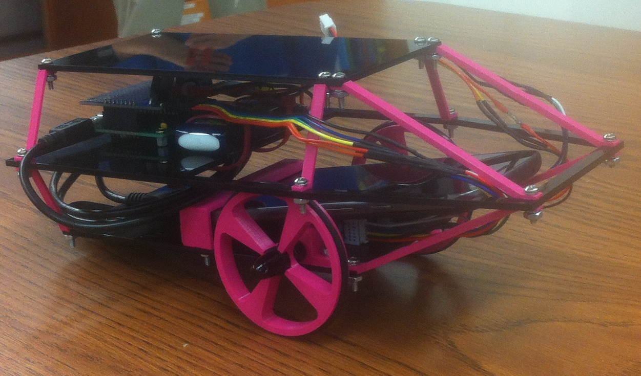
Chassis
I designed and fabricated the components for the drone chassis from scratch with compactness and visual appeal as primary concerns. Three mounting plates provide locations to affix electronics and components. These are made of acrylic plastic and were produced on a laser cutter. Wheels, brackets, and support elements are 3D printed from PLA plastic. All CAD modeling for these components was done in Onshape, an online sister product of Solidworks. One plastic spoon provides a low friction contact point with the ground to allow for balance using only two wheels. By using a multi-level chassis I was able to produce ample space for mounting components while maintaining a small footprint and an aesthetically pleasing design.

Electronics
The onboard electronics for this project consisted of a custom PCB for a PIC32 microcontroller and mounted motor driver shield; off the shelf circuit components, motors, and wiring; a 6V rechargeable LiPo battery; and a Moto G cell phone running the Android operating system.
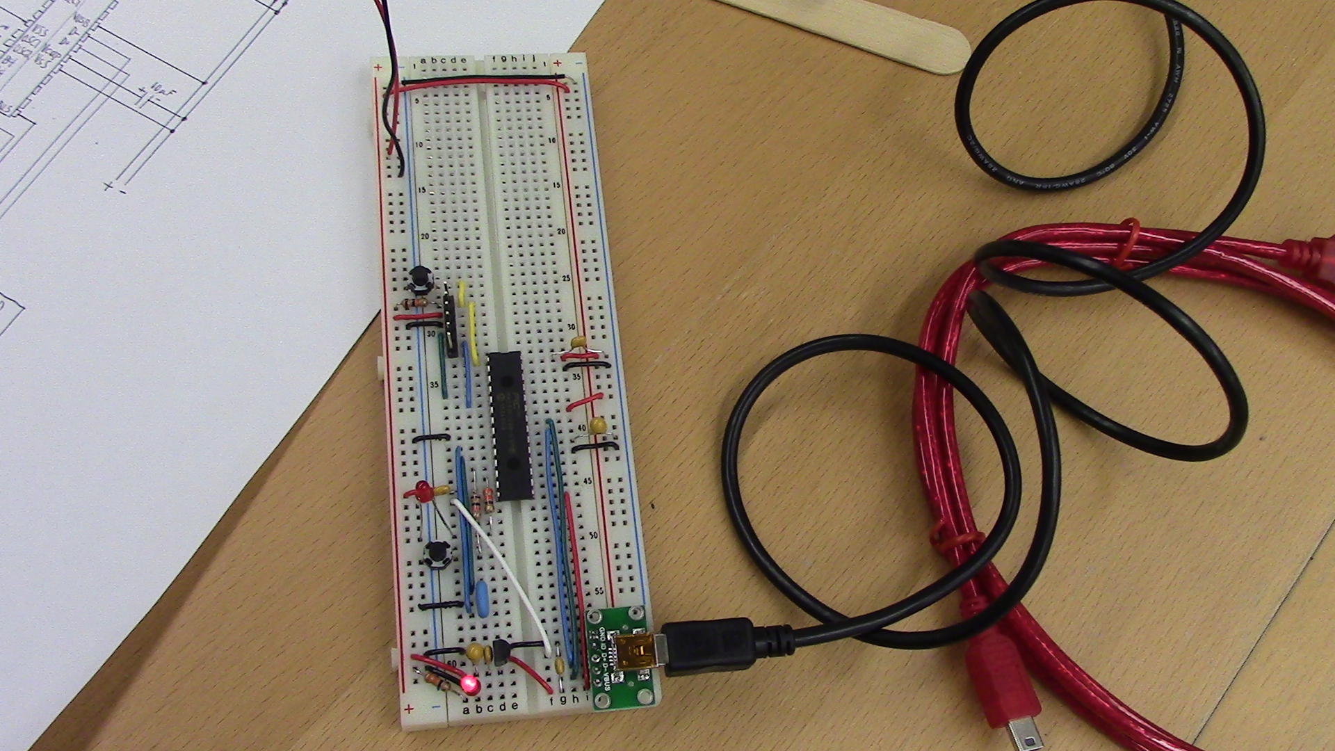
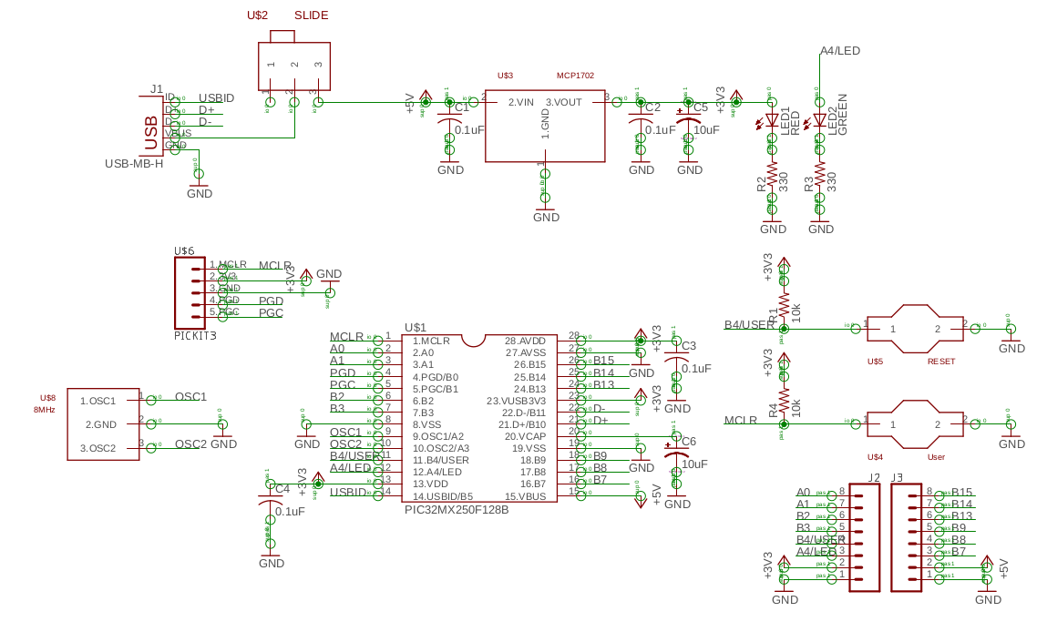
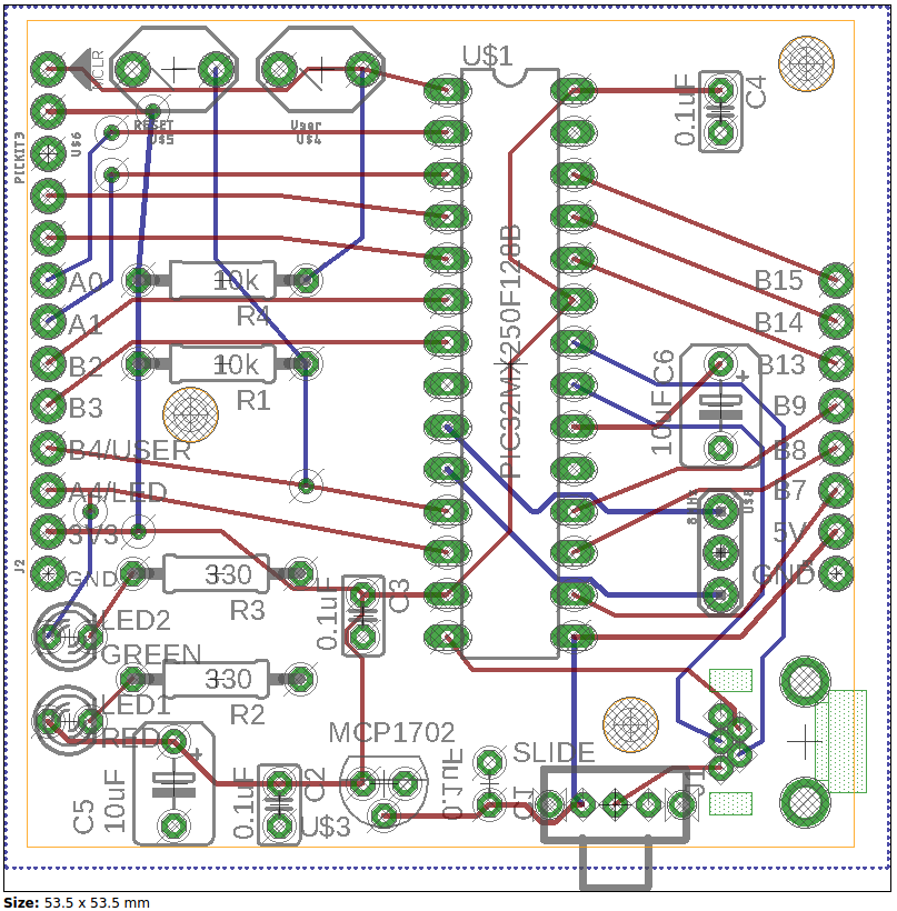
I designed the microcontroller PCB in Autodesk Eagle to greatly and cheaply reduce the size and wiring complexity of using the PIC32 for motor control on this project.
The Moto G provided all the electronics necessary to perform image processing and provide the PIC32 circuit board with power and data using a USB OTG connection.
Power for the motors was provided by the 6V battery routed through the motor control shield.
Software
My software for the project consists of 3 primary components. The PID motor controller and the USB communications handler are programmed in C and run on the PIC32 microcontroller. The computer vision component is programmed in Java and runs on the Moto G. Data transfer from the Moto G to the PIC32 is performed through Serial over USB communications. The USB communication component handles these communications on the PIC32 end, while built in Android functions are used on the MotoG.
Motor Controller
The motor control algorithm is a C program running on the PIC32 as a 500Hz interrupt. The algorithm has a control loop for each wheel which determines current wheel velocity by applying a moving average filter to wheel encoder data, compares this value to the desired wheel velocity to calculate error, applies a PI control calculation to determine an appropriate PWM duty cycle, and sets the relevant PWM generator accordingly.
USB Communication Handler
The USB communications handler is an algorithm that runs in C on the PIC32, as part of a large state machine that handles the PIC32’s operations. I wrote this section of the state machine to handle data transfer to and from the Moto G. The program receives regular Serial over USB transmissions containing a center of mass (CoM) value for the red pixels on row 240 of the images taken by the Moto G. The algorithm presumes this to be the center of the red line being followed, and compares it to the line’s desired position in the middle of the image in order to determine an error value. A P controller is then used to calculate a desired velocity for each wheel that will correct the drone’s heading to center the line. The Moto G’s end of the USB communication is handled by functions built into the Android OS.
Computer Vision Processor
The computer vision processor algorithm is an event based program that runs in Java on the Moto G. Whenever a new image is received from the Moto G’s camera the algorithm acquires the pixels from the middle row of the image, uses thresholding to determine which pixels are red, and calculates a center of mass (CoM) value for the red pixels in that row. The CoM is then sent to the PIC32 through Serial over USB using functions built into the Android operating system. A GUI allows the user to set the range and minimum threshold for “red” dynamically using slider bars, displays the image with a point overlayed on the calculated CoM, and displays a running history of data echoed back from the PIC32 to confirm that communications are open.