Receding Horizon CNC Interface
June 15, 2018
| Key Skills & Tools | ||
|---|---|---|
| GRBL | Microprocessors | |
| Linux | ROS | |
| CNC | Computer Vision | |
| C++ | Rviz | |
| Python | Receding Horizon Control | |
| GCode | CAD (Onshape) | |
| Feedback Control |
Github Repo
https://github.com/idtx314/mill_controller
Project Introduction
On this project I worked with researchers to produce a project outline, built a trajectory execution simulator, designed and built a research platform, created a modular feedback control program and computer vision processor that was capable of receding horizon control, coordinated control interfaces with researchers, built a GUI, and extensively documented the system and appropriate usage.
The project was undertaken to support the research of Ahalya Prabhakar, who studies information based trajectory generation and receding horizon control systems with the goal of producing more adaptive, graceful robots.
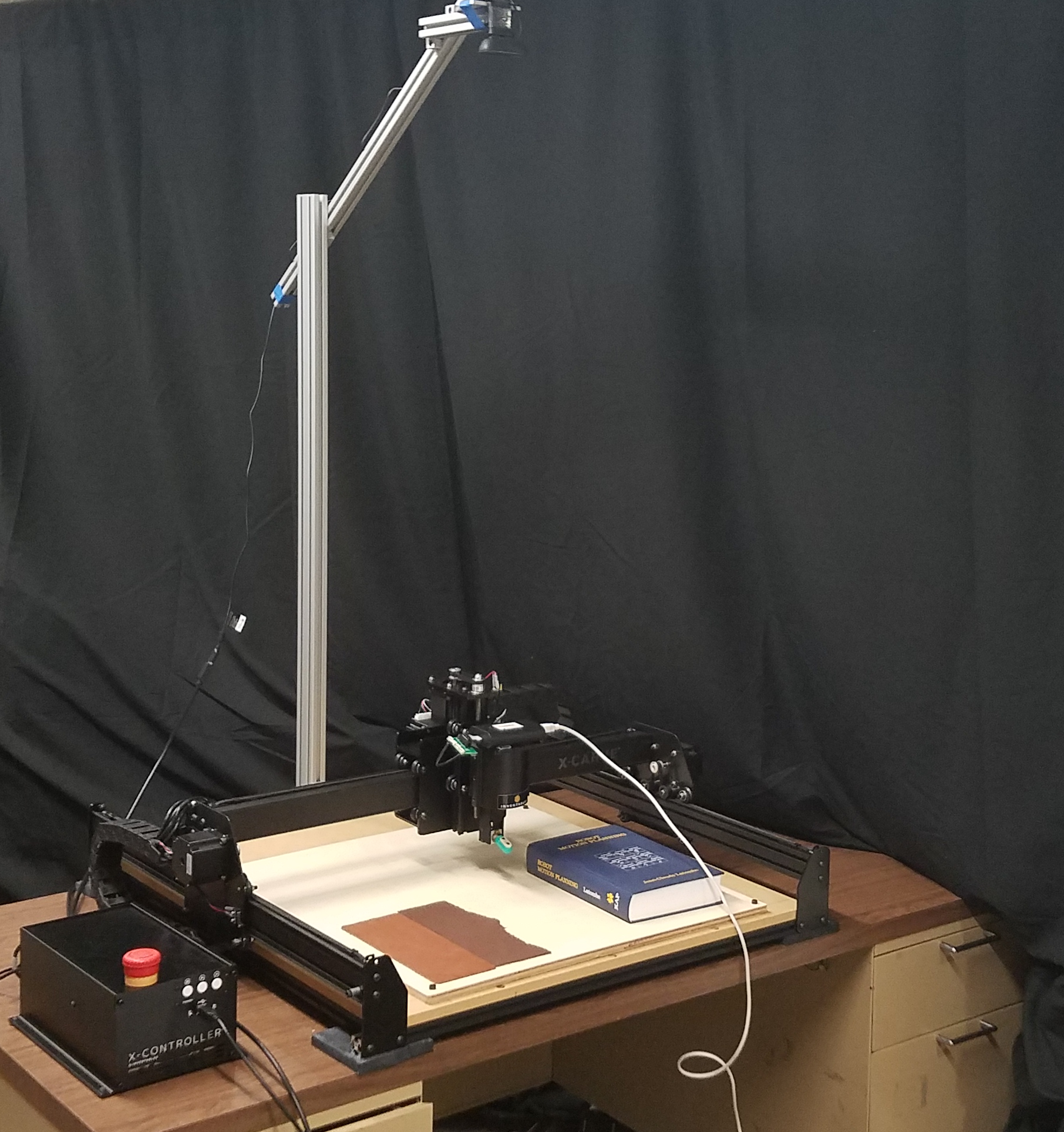
Hardware
The experimental platform is based on an X-Carve CNC mill and X-Controller, all purchased as a kit from Inventables. I modified the platform by attaching an articulated arm to the back. The arm can be easily configured to reach various heights and mount a variety of sensors over the carving bed.
Significant Design Choices
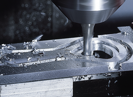
Carving/Printing
A mill was selected over alternative CNC platforms on the rationale that removing material would allow trajectories to be generated with the least constraint in the base scenario. This was in comparison to other methods like 3d printing, which would require that any trajectories produce a structurally stable product from nothing.
Axis Count
After researching available milling platforms, I selected a 3-axis X-Carve CNC system that was among the existing lab equipment rather than purchasing a full 5-axis system. The 3-axis system was expected to be significantly easier to control, and thus more suitable for an initial prototype. It was also immediately available, removing the need to order and assemble a new sysem.
Sensor Selection
A variety of cameras and depth cameras were examined while choosing the sensor for the platform. A Logitech C270 color USB camera was selected for use in the initial prototype, which only required color recognition. To accomodate the expected switch to a depth camera later in the project’s development, I designed the image processing algorithms to work with point cloud data as well.
Sensor Mounting
A motorized camera mount was briefly considered to allow all relevant sides of the material to be imaged. Because mill systems that can carve more than one side of a material typically move the material rather than the end tool, I concluded that moving the camera would also be uneccesary.
Software
The control software is designed as an interface between prototype trajectory generators and the experimental platform. To make future development as easy as possible, I prioritized modularity in the design.
Individual functions of the controller are split out into separate ROS nodes, which can be replaced or modified at will with little fear of compromising the rest of the system. This also permits any given node to be written in either Python or C++, granting access to the libraries and features available to both languages.
There are three primary functions: trajectory parsing, gcode sending, and image processing.
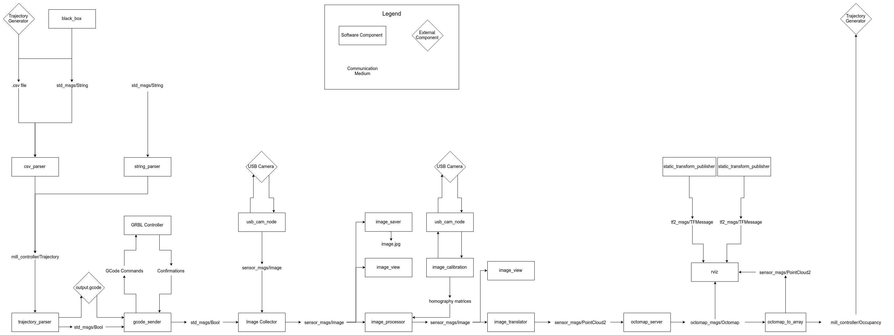
Trajectory Parsing
To maximize ease of user input, the system can parse a variety of input types into a 3 dimensional, time dependent trajectory. This data is then translated into a Grbl compatible G-code file for execution on the X-Controller.
G-Code Sending
The sending nodes communicate with the X-Controller through a serial over USB connection. After preparing the X-Carve for use, the sending node streams the G-Code file line by line and receives confirmations from the X-Controller. Streaming will continue until the trajectory ends or the time horizon has been exceeded.
Vision Processing
The vision processing nodes use OpenCV, the Point Cloud Library, and the Octomap library to process sensor data from a Logitech C270 USB camera into a variety of output formats. These outputs are a three dimensional representation of how the experiment material has changed as a result of the end-effector following the input trajectory. Experimental trajectory generation software can use this information to alter the planned trajectory for future timesteps in order to better achieve the intended final outcome.