Quadrotor Chassis and Mixed-Autonomy Controller
March 23, 2018
| Key Skills & Tools | ||
|---|---|---|
| IMU (MPU-9250) | PID Control | |
| Motor Control | C | |
| Microprocessors (Raspberry Pi) | Group Work | |
| SSH | Electronics | |
| Sensor Fusion | State Estimation | |
| Feedback Control | Mechatronics |
Repository
The project is written mostly in C. The final codebase is available on my github repository here.
Introduction
Quadcopters have become common platforms for research, industry, and leisure. Some of this ubiquity is surely due to their stability and ease of use, and it might suprise many to learn that these properties aren’t inherent to the design. The eerie grace of a well made quadcopter is actually a result of its intricate control algorithms, and building such a platform is an opportunity to learn about these algorithms first hand.
The goal of this project is to assemble a small quadcopter and program control software that will respond to control input from the user, but hover in place when left to operate autonomously.
This project course was tackled in groups of two. Over a ten week period, Drew Warren and I followed the guidance of the course material to produce an air worthy chassis and program control code that responded well to user input over a wireless network. Horizontal autonomous position holding was accomplished using fusion of onboard sensor data and positional information provided by a Vive lighthouse observing the flight.
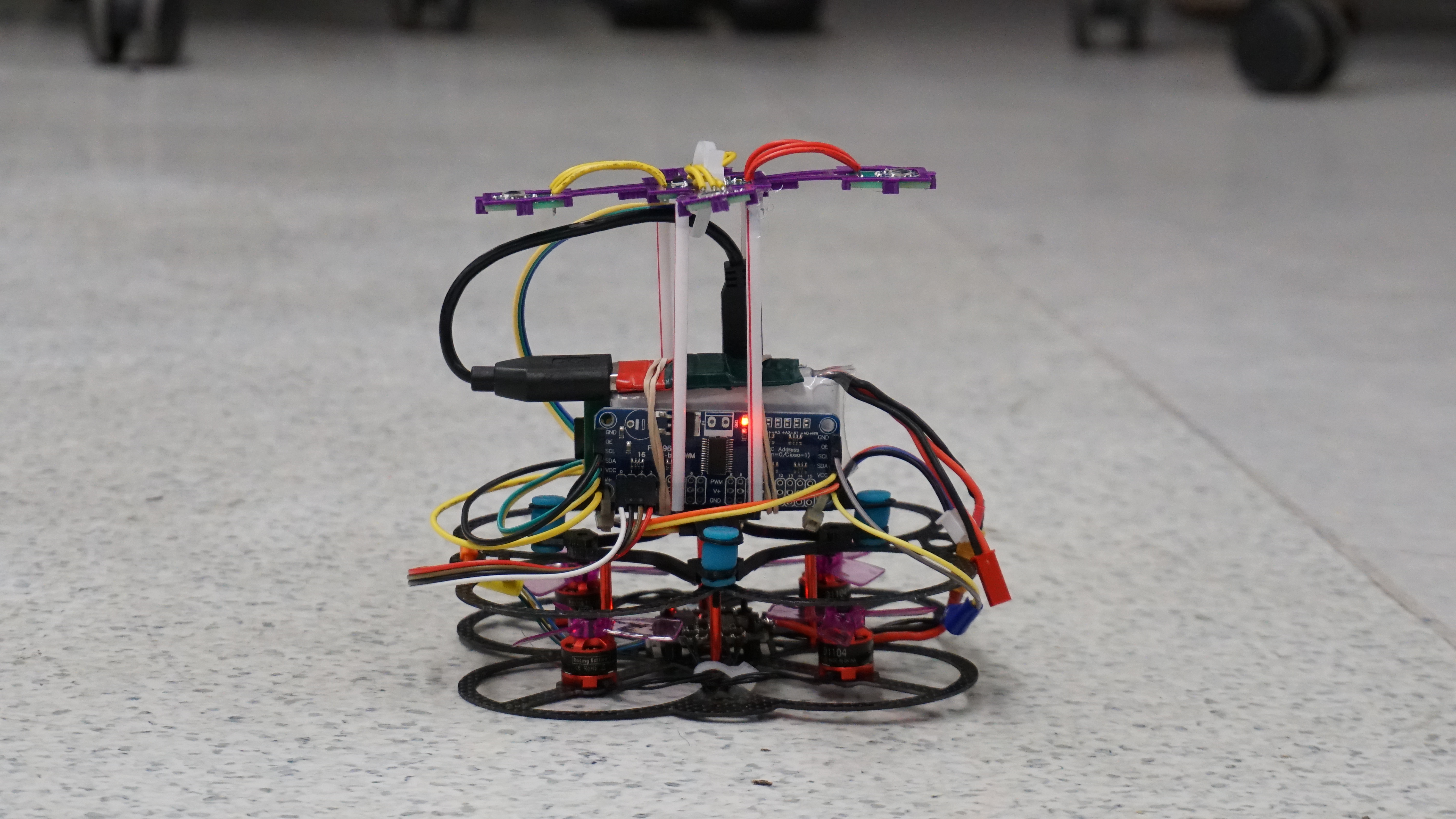
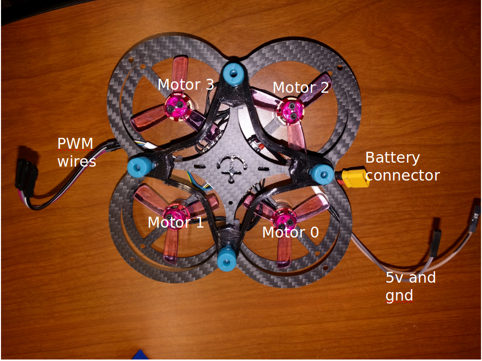
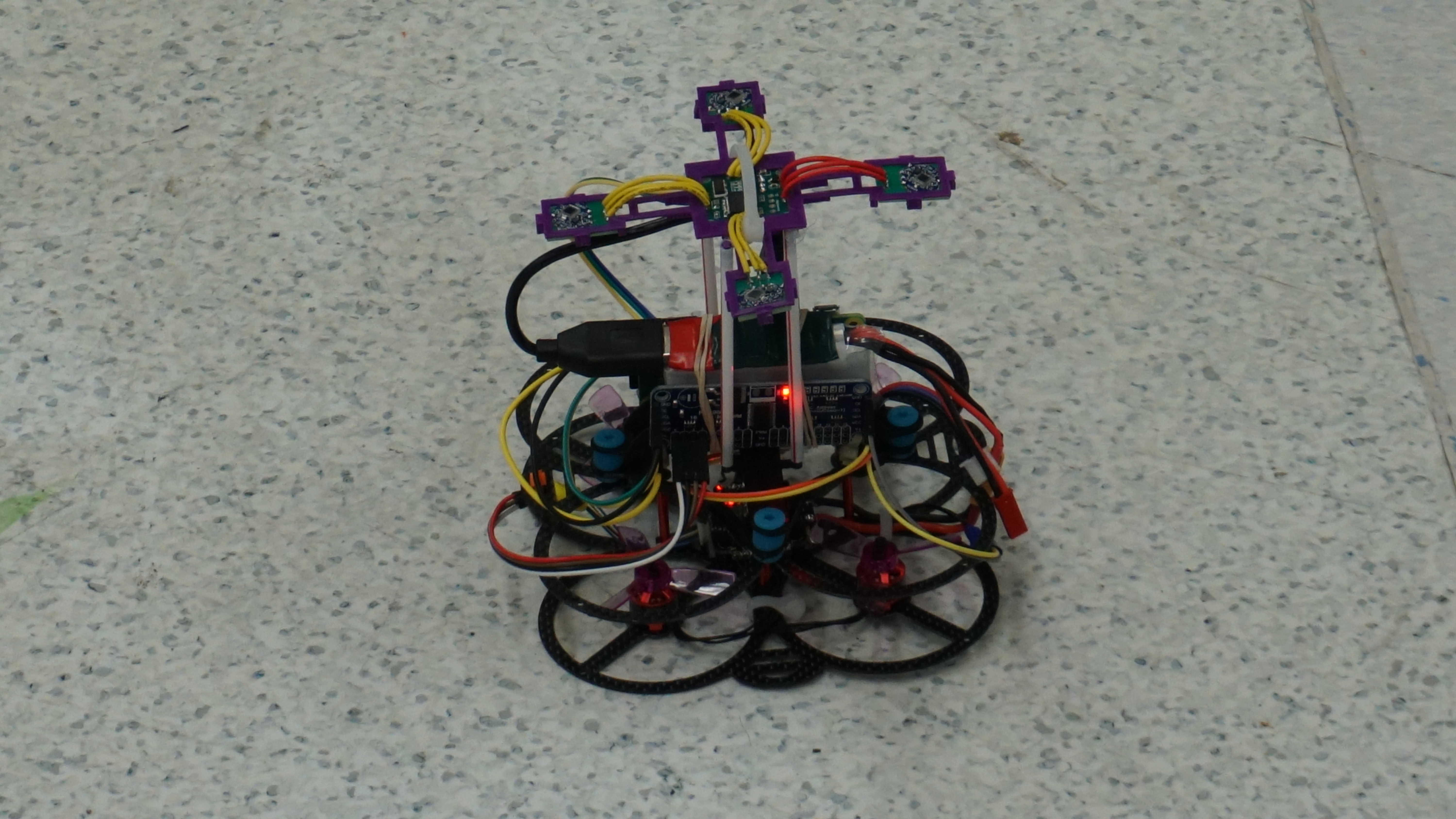
Hardware
The upper chassis is composed of a Raspberry Pi Zero, a PWM control board, a rechargeable LiPo battery, and a 3D printed plastic frame. I performed assembly of these components and attached them and a 6 axis IMU to the provided lower chassis, which includes a larger frame and 4 motors attached to an ESC board. A wireless network card and battery charge alarm are attached to the upper chassis and secured loosely. Communication between hardware components is handled using I2C protocol.
A quartet of infrared sensors is suspended above the upper chassis. These sensors detect regular IR sweeps broadcast by a Vive Lighthouse positioned above the flight volume. The IR data can be used to facilitate autonomous position holding.
During development of the PID controllers for roll and pitch I also constructed a 1 degree of freedom testing rig. This was extremely simple, consisting of clamps and plastic line suspending the quadcopter between two tables, but it worked admirably.
Software
The control software is written in C, and runs on a Raspberry Pi microcontroller with Linux installed. Low level motor control and communications are handled by pre-built functions and libraries. My own algorithms are responsible for the higher level system functions, which consist of two main duties: Localization and Control.
Localization
The localization algorithms use sensor input to determine the position and orientation or the quadcopter. Pitch and roll are determined by integrating data from the onboard gyro and combining it with data from the onboard accelerometer using a complementary filter. Alpha for the filter was determined experimentally. In my build, the gyro data is heavily favored. Approximate yaw rate is determined based on just the onboard gyro data.
The position of the quadcopter in space and its absolute yaw is calculated by using data from the IR sensors and Vive Lighthouse. The Lighthouse regularly sweeps the flight volume with two distinct waves of infrared light, one horizontal and one vertical. The timing of the Lighthouse’s IR sweeps is recorded by the sensors. This timing data and the known geometric relationships between sensors is used by pre-built algorithms on the Pi to determine the x, y, z, and theta of the sensor array in an inertial reference frame established relative to the Vive. All data calculated by the localization algorithms is made available to be used by the control algorithms.
Control
The control algorithms use the pose data provided by localization to determine input values for layers of PID controllers. The errors between the x, y, and absolute yaw of the quadcopter and a reference position and orientation are used in a set of level 1 PID controllers to determine desired control values for roll, pitch, and yaw rate. The desired roll, pitch, and yaw rate are weighted and combined with user input received over the wireless card in a 50/50 ratio. This allows the user to influence the quadcopter’s controller, but not override it, an approach known as “mixed autonomy”.
The combined roll, pitch, and yaw rate targets from the user and the level 1 controllers are then compared to the actual roll, pitch, and yaw rate values from localization to set the error in the level 2 PID controllers, whose output is weighted and combined to determine desired control values for individual motor duty cycles.
Control of the z-axis position is notably absent from these algorithms. Regulating the z-axis was a part of the original project goals, but we found that implementing this part of the controller compromised the stability of the parts responsible for x-axis and y-axis control. I believe this is a result of flaws in the control algorithms that make the calculations very sensitive to the execution time of the control loop. I noted these shortcomings as we built the controllers and was able to reproduce the instability, but attempts to resolve the issue encountered unexpected difficulty and due to the time constraints of the project we elected to continue using the algorithms as described in the course material.
Future Work
- Improve control algorithms to properly account for execution time.
- Build a more robust chassis with a more reliable center of mass.
- Install additional sensors and use them to reduce reliance on external sensors when determining yaw and position.
- Implement more complex automated behavior, like flight path execution.
- Implement automated landing and takeoff.