CoffeeBot for Baxter
March 23, 2018
| Key Skills & Tools | ||
|---|---|---|
| Baxter | Inverse Kinematics | |
| ROS | Python | |
| Group Work | Computer Vision |
Repository
The git repository for this project is available here.
Introduction
Coffee making is a necessary, but highly repetitive process. So when tasked with demonstrating our skills with the Robot Operating System (ROS) and robotics, my group of 4 students (Kashish Goyal, Lauren Hutson, Solomon Wiznitzer, and I) decided that we would automate coffee making.
To bring the scope of the project in line with our time frame we set the goal of having a robot operate a Keurig coffee maker and accompanying items like cups and pods. We set an additional goal of having the robot use visual processing to identify objects, allowing them to be placed anywhere in the workspace
Over the course of 2 weeks we used a combination of color recognition and AR tag tracking to accomplish object recognition, created nodes and services for trajectory planning and execution, tied our individual work together into a functioning whole, and presented our project to students and faculty.
Hardware
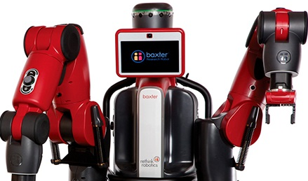
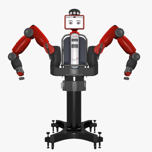
We selected the Baxter robot as the project platform both because it met all hardware requirements for the project and because it was the most likely of our potential platforms to be available for use at any given time, allowing more freedom in development scheduling.
Baxter was produced by Rethink Robotics for research and academic use. The platform consisted of two arms and a swivel mounted “head”, all three of which were equipped with a sensor suite that included a color camera. The arms could mount a selection of grippers, and the robot’s API was reasonably well documented by the manufacturer. The most significant drawback of the platform was that it used series elastic actuators, which are known to be less precise in their motions.
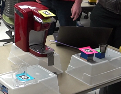
With only two weeks to complete the project, it was decided to limit the scope of the problem where possible and then expand if time allowed. By using a Keurig single serve automatic coffee maker, the project outsourced some of the most complicated aspects of coffee making and was able to focus on a smaller set of motions and interactions.
Software
The control sofware used a ROS based archicture, with major functions of the system being handled by indiviual nodes on either Baxter or the control station. We divided the overall architecture into 3 main components: general trajectory planning and execution, trajectory planning and execution related to operating the Keurig, and vision processing. Each of these components was assigned to 1 or 2 programmers.
After dividing the labor of software development, we initially deferred the planning of component integration. We assumed that this would be a minor issue that could be resolved at the end of the project. However as our status meetings continued, and as I faced the question of how to best design my own component to fit into an overall structure we hadn’t established, I began to push for a more formal plan.
My insistence ultimately led to us officially laying out the basic structure of the project, declaring the general trajectory planner as the main control node, and better defining the interfaces through which other nodes should be called.
We were able to integrate our components reasonably smoothly at the conclusion of the project, though we did overlook some critical aspects. In particular, we discovered too late that both trajectory planners used the left arm, but required different gripper sizes to complete their tasks.
Main Control Node
The primary control node was the central node of the system, responsible for initializing the system, handling all calls, and passing data to and from other nodes.
As a result of its originally being the general trajectory planning and execution node, the main control node was also responsible for commanding some motions of the robot based on transformations provided by the vision processing node. In particular, this node handled the moving of cups and other items to and from the Keurig. Joint trajectories for these motions were generated through inverse kinematics solving.
Auxiliary Control Nodes
The Auxiliary control nodes provided ROS services responsible for motions directly related to operating the Keurig, such as opening the lid or pressing the start button. By using transformations provided by the vision processing node, all actions could be taken relative to the location of the Keurig, allowing the coffee maker to be placed anywhere in the workspace so long as Baxter could reach it easily.
Like the main control node, these nodes used inverse kinematics to plan their motion. However, I intentionally leveraged short motion distances and reference starting positions in order to avoid the circuitous joint trajectories often seen in IK planning.
I chose to build the nodes as ROS service providers so that they could be easily integrated once we established an architecture for the control software. This also allowed me to take advantage of the call/wait behavior of ROS service calls to ensure that the main control algorithm wasn’t running ahead of Baxter’s movements.
Vision Processing Node
When called, the vision processing nodes were responsible for locating relevant objects in the workspace and reporting their positions back to the main control node for use in trajectory planning.
These nodes used an arm camera to achieve an overhead view of the work space and a combination of color image processing with OpenCV and AR tag tracking with the ROS package ar_track_alvar to determine the location and identity of objects in relation to Baxter. This allowed items to be placed at positions that were not pre-determined, subject to the constraint that Baxter could actually reach them.
Future work
- Improve trajectory planning to avoid undesirable plans.
- Re-write of main control node to act as central controller only.
- Re-write all movement calls as services or actions.
- Implement more advanced object recognition to remove reliance on AR tags.
- Switch robot motions to different arms based on gripper requirements.
- Implement visual servoing to correct for imprecision in actuators.