Mag-Sense Wearable Device
March 23, 2018
| Key Skills & Tools | ||
|---|---|---|
| Microcontrollers (Arduino) | Sensor Fusion | |
| Programming (C, Python) | Communications (Serial, I2C) |
Repository
Arduino Code
ROS Code
CAD Files
Introduction
In this project I created and proposed the project concept of a device that would allow a user to “feel” magnetic fields; selected a microcontroller, IMU, and motor; soldered and wired together the electronic components; designed wearable hardware in CAD; fabricated prototypes with 3D printing; wrote software in C to read from sensors, apply motor control, estimate state using sensor fusion, and communicate state estimates over serial; wrote software in Python to visualize state estimates using ROS and Rviz; and refined the hardware and software through failure analysis and user testing.
Hardware
Hardware for this project is divided into a set of wearable mounts and the onboard electronics.
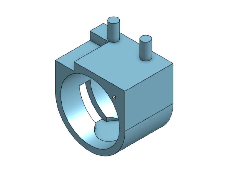
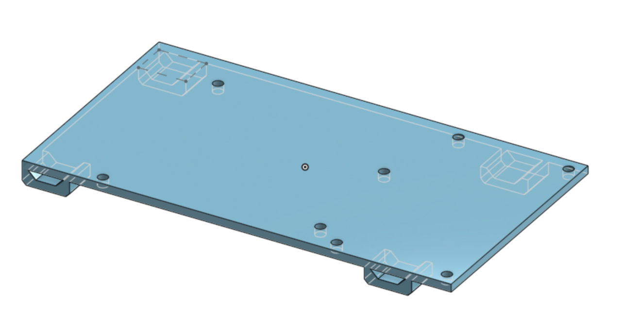
Wearable Mounts
Two small mounts secure all the project components into a complete package, which is designed to be worn on a user’s person. A ring holds the sensor and feedback motor, while all other components are mounted onto a plate, which is secured to the forearm with velcro straps. My design allows the user to focus all their attention onto the finger when attempting to “feel” a magnetic field while minimizing the perceived weight of the package. All CAD modeling for these components was done in Onshape, an online sister product of Solidworks. Prototypes were 3D printed from PLA plastic.
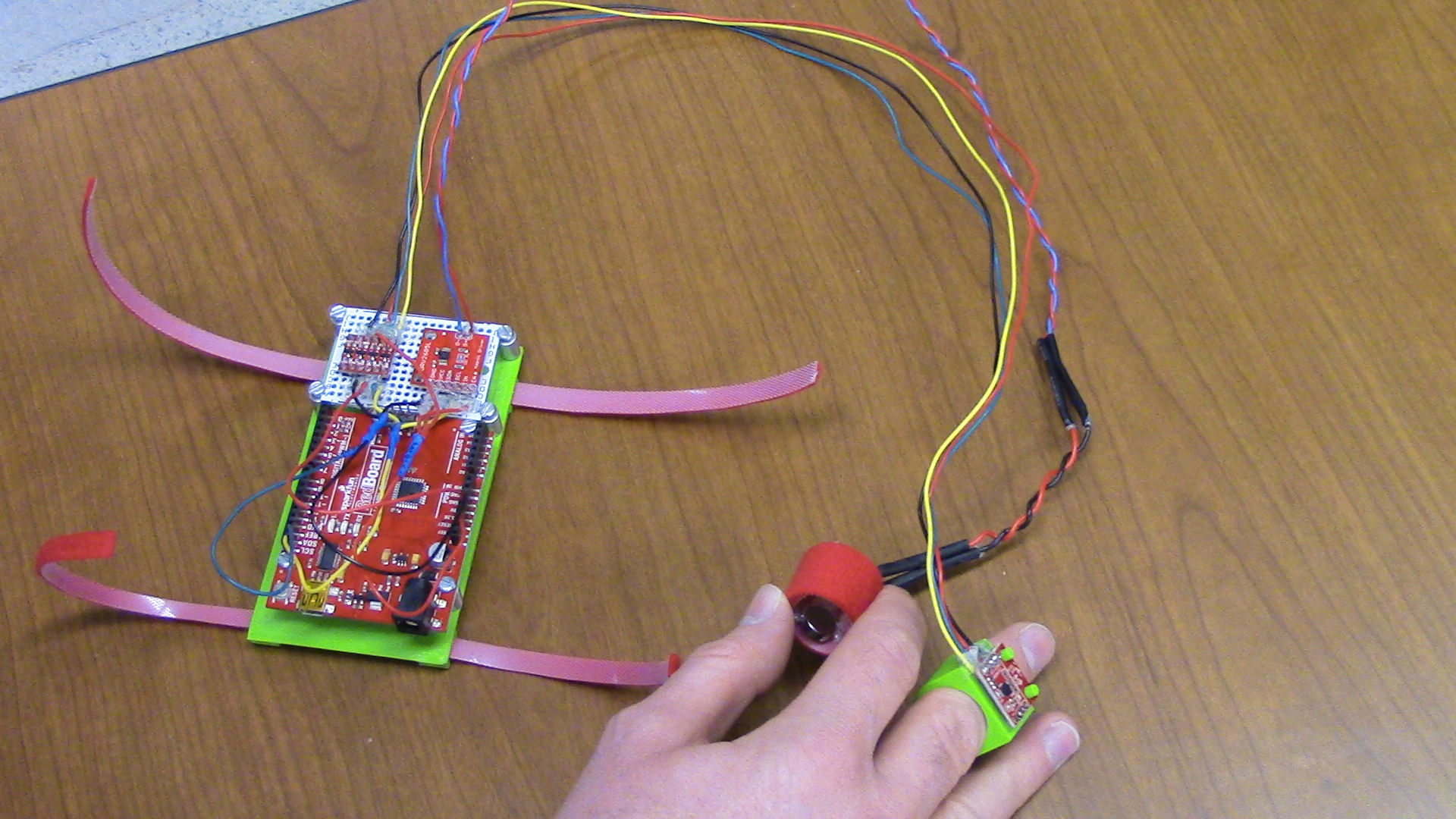
Electronics
The electronics for this project consist of an Arduino microcontroller PCB, a logic converter PCB, an MPU-9250 9-axis IMU (with accelerometers, gyros, and magnetometers), a motor driver PCB, and an Eccentric Rotating Mass (ERM) motor for haptic feedback. The IMU and motor are mounted on the ring mount. The Arduino, logic converter, and motor driver boards are mounted on the forearm mount. Soldered connections between these components use multi-stranded wiring for flexibility and are reinforced with heat shrink tubing and adhesive. Power and serial communications are provided by the USB port on the Arduino.
Software
The software for this project performs four primary functions: IMU calibration, data collection and state estimation, motor control, and state visualization. Most functions are handled on the Arduino microcontroller, with visualization being performed by a ROS node intended to run on an attached Linux system.
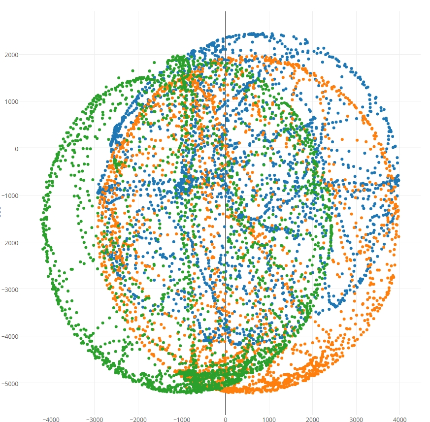
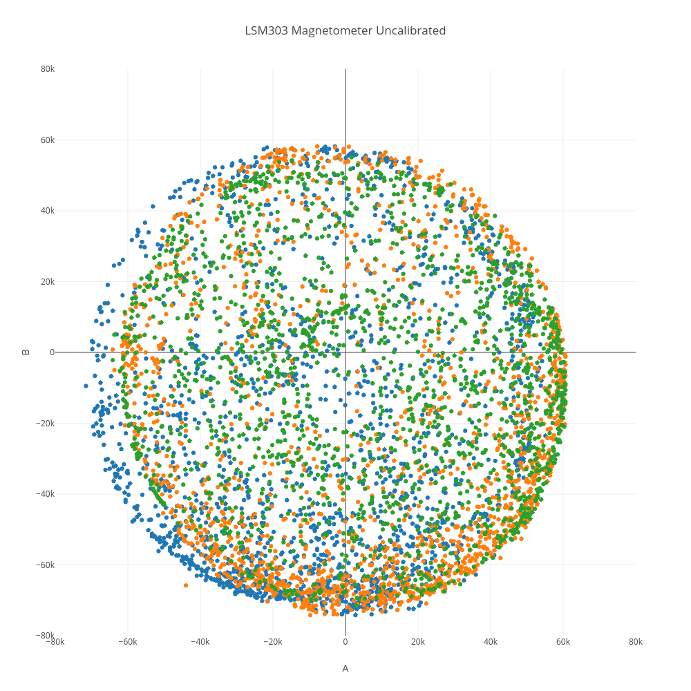
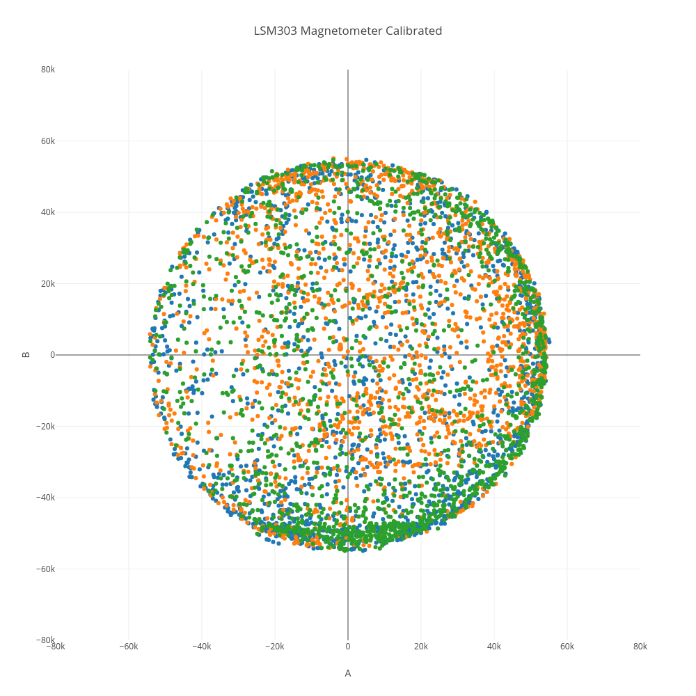
IMU Calibration
The IMU calibration algorithm is written in C on the Arduino, and runs during the microcontroller’s initialization. The algorithm calculates bias values for the accelerometers and gyros using at rest readings, then performs hard iron and soft iron calibration of the magnetometer’s hall sensors to co-locate the reading centers and normalize the reading surface to an ellipsoid.
Instructions on when and how to move the IMU during calibration are provided over serial, and will be printed to the terminal if received by the ROS node made to handle serial communications.
Significant portions of the calibration code were provided by Kris Winer, whose libraries were helpful for learning to use the IMU.
Data Collection and State Estimation
The state estimation algorithm is written in C on the Arduino, as part of the looping program. Data from the gyro, accelerometer, and magnetometer registers is read from the IMU using I2C communications protocol.
The gyro data is integrated over time to produce an estimated change from the initial orientation of the IMU. Accelerometer data is used to estimate roll and pitch based on the direction of gravity, and these estimates are combined with the gyro values using a complimentary filter in order to correct for the compounding error created by integration.
The final estimated orientation is broadcast using Serial protocol over the USB port, along with the magnetometer readings.
Motor Control
The motor control algorithm is written in C on the Arduino, as part of the looping program. Vibrations of different frequency and pattern are commanded based on the magnitude of the magnetic field detected by the IMU, in order to indicate the approximate strength of the field to the user.
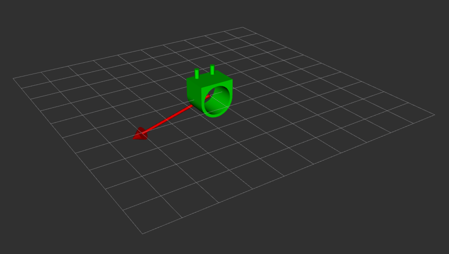
State Visualization
The magnetic field and IMU data is visualized using a pair of ROS nodes programmed in Python, and intended to run on a computer connected to the Arduino via USB.
The first ROS node listens for serial communications containing orientation data over the USB port and translates the contents into a ROS message. The second ROS node receives that message and uses the data to publish visualization markers for the magnetic field strength and direction, and the orientation of the IMU compared to its initial position. These markers can then be visualized using Rviz.